
Camlock Size Chart: Measure Once, Order Right
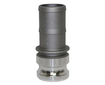
Measure across the adapter groove to identify nominal size.
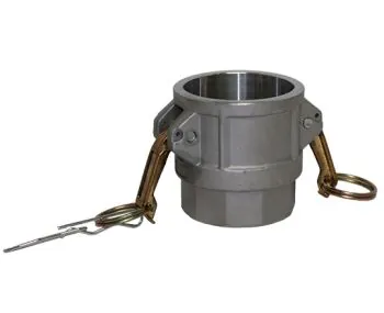
Coupler bore and arm spacing must match the same nominal size.
What a Camlock Size Actually Means
Camlock sizes describe the nominal bore of the hose or pipe the coupling is designed to connect — not the outside diameter of the fitting, and not the outside of the hose. A 2” camlock clamps onto 2” hose. That is the whole trick, and it is where most order mix-ups start.
When we say a coupling is “2 inch,” we mean its hose shank is built to receive hose whose nominal inside diameter is 2 inches (50.8 mm). The same nominal size runs through every camlock style, whether it is a female coupler (Type B, D, F), a male adapter (Type A, C, E), or a hose shank fitting. Size is the language that makes all the styles interoperable: a Type A male adapter and a Type D female coupler both carry the same nominal size, and that is exactly why they connect.
Nominal sizes follow the inch-based pipe and hose conventions used throughout North American fluid handling. The standard range runs from 1/2” through 6” in half-inch and one-inch steps, with a 2-1/2” size sitting between 2” and 3”. Each nominal size corresponds to a metric bore: 1/2” is 12.7 mm, 3/4” is 19.05 mm, 1” is 25.4 mm, 1-1/4” is 31.75 mm, 1-1/2” is 38.1 mm, 2” is 50.8 mm, 2-1/2” is 63.5 mm, 3” is 76.2 mm, 4” is 101.6 mm, 5” is 127 mm, and 6” is 152.4 mm.
Because the size refers to the bore, the physical outside of the coupling always measures larger than its name. A 2” male adapter measures roughly 2-1/2” across its widest point at the groove. If you measure a coupling with a tape and order that number, you will end up with the wrong size. This guide gives you the full size table, the correct measuring method, the flow and pressure behavior of each size, and the pairing rules that prevent mistakes.
Full Camlock Size Reference Table (1/2” to 6”)
The table below lists every standard camlock size with its nominal bore in millimeters, the typical outside diameter range you will see on standard reinforced hose of that size, a practical flow reference for low-pressure transfer, and the duty each size is most commonly used for.
| Size | Nominal bore (ID) | Typical hose OD range* | Flow reference (low-pressure transfer) | Typical application |
|---|---|---|---|---|
| 1/2” | 12.7 mm | 0.7” – 0.8” | ≈ 12 gpm | Sampling lines, homebrew, lab, small air lines |
| 3/4” | 19.05 mm | 1.0” – 1.1” | ≈ 25 gpm | Washdown, rinsing, pilot plants, small pumps |
| 1” | 25.4 mm | 1.3” – 1.5” | ≈ 45 gpm | Chemical drum transfer, transfer skids, small pumps |
| 1-1/4” | 31.75 mm | 1.6” – 1.8” | ≈ 60 gpm | Irrigation sub-mains, moderate transfer |
| 1-1/2” | 38.1 mm | 1.9” – 2.1” | ≈ 80 gpm | General transfer, fire reels, pool pumping |
| 2” | 50.8 mm | 2.4” – 2.7” | ≈ 150 gpm | The workhorse — pumps, tankers, irrigation, dewatering |
| 2-1/2” | 63.5 mm | 2.9” – 3.2” | ≈ 230 gpm | Larger pumps, tanker offload, heavy irrigation |
| 3” | 76.2 mm | 3.5” – 3.8” | ≈ 300 gpm | Tanker loading, dewatering, fire supply |
| 4” | 101.6 mm | 4.4” – 4.8” | ≈ 500 gpm | Bulk transfer, manifolds, frac/water transfer |
| 5” | 127 mm | 5.5” – 5.9” | ≈ 800 gpm | Large bore bulk, municipal water supply |
| 6” | 152.4 mm | 6.5” – 7.1” | ≈ 1,000+ gpm | Large bore bulk, dredging, flood control |
* Hose outside diameter varies with wall thickness and reinforcement. A thin-wall lay-flat hose runs at the low end of the range; a heavy suction hose with a wire helix runs at the high end. You always select by inside diameter (the nominal bore), never by the outside.
Flow references assume a short hose run at roughly 2–5 m/s fluid velocity, typical of gravity-fed or moderate pump transfer. Actual flow depends on pressure, hose length, internal roughness, fluid viscosity, and elevation — the table is a sizing guide, not a rated capacity.
Standard camlock stock coverage by material: aluminum and stainless steel are commonly available in every size from 1/2” through 6”. Polypropylene runs 1/2” through 4”. Brass runs 1/2” through 4”. For the exact pressure capability of each size and material, see our pressure rating chart.
Nominal Bore vs Outside Diameter: The Distinction That Saves Orders
Three different dimensions exist on any hose-to-coupling connection, and confusing them is the number one cause of wrong orders:
- Hose inside diameter (bore) — the fluid passage. This is the number that matters. A 2” hose has a 2” bore, and it needs a 2” camlock.
- Hose outside diameter — the physical outer measurement of the hose wall. It varies with wall thickness and reinforcement and tells you nothing about the coupling size.
- Coupling outside diameter — the widest point of the fitting body, including the cam arms and groove. Always larger than the nominal size. On a 1-1/2” coupling, for example, the body measures about 1-3/4” to 2” across, and the arms extend beyond that.
The hose shank of a camlock is machined so its barbs seat inside the hose bore. When the hose clamp is tightened, it compresses the hose wall into the barb profile, gripping the hose firmly. The barb diameter is engineered around the nominal bore of the hose — not the hose OD, and not the coupling body. That is why a 2” coupling will not accept a 2-1/2” hose no matter how hard you tighten the clamp, and why a 2” hose fitted with a 1-1/2” camlock leaves a gap and leaks or blows off under pressure.
How to Measure Camlock Size Correctly
You can identify the size of any camlock, hose, or threaded connection in about sixty seconds with a ruler, a tape measure, or a caliper. The rule is simple: measure the inside of the female end or the bore of the hose, never the outside of the fitting.
Measuring a female coupler (Type B, D, or F)
Open the coupler so you can see the bore. Measure the inside diameter at the sealing face — the flat surface where the gasket sits — or across the bore at the coupling’s narrowest point. A 2” female coupler measures about 50 mm (2.0”) across the bore; a 1-1/2” coupler measures about 38 mm. If the bore measures 48–52 mm, the size is 2”. If it measures 60–65 mm, the size is 2-1/2”. If it measures 73–78 mm, the size is 3”. The nominal sizes map to these approximate bore readings:
| Ordered size | Bore you should measure | |
|---|---|---|
| 1/2” | ≈ 12 – 13 mm | |
| 3/4” | ≈ 19 mm | |
| 1” | ≈ 25 – 26 mm | |
| 1-1/4” | ≈ 31 – 32 mm | |
| 1-1/2” | ≈ 38 mm | |
| 2” | ≈ 50 – 51 mm | |
| 2-1/2” | ≈ 63 – 64 mm | |
| 3” | ≈ 76 mm | |
| 4” | ≈ 101 – 102 mm | |
| 5” | ≈ 127 mm | |
| 6” | ≈ 152 mm |
Use a digital caliper for precision. A tape measure works but adds a few tenths of a millimeter of error; if you land between two sizes, round to the nearest nominal size, then confirm with the millimeter values above.
Measuring a male adapter (Type A, C, or E)
Male adapters are easiest to size at the shank or the coupling end. Measure the inside of the threaded end (for an adapter with female threads) or measure the outside of the hose shank, then compare it to the shank dimensions for your candidate size. The most reliable check is the groove diameter: measure the outside diameter at the groove that receives the cam arms. On a 2” male adapter, the groove-end OD is roughly 2-1/4” to 2-3/8”. If you have a female coupler of a known size on hand, the definitive test is simply to try the connection — same-size male and female camlocks seat together with the cams closing smoothly over the groove.
Measuring a hose
Read the label first. Almost all transfer hose is printed or embossed with its nominal size every few feet — “2"”, “50 mm”, or both. Trust the label, verify with a ruler. To measure manually, insert a ruler or caliper jaw into the end of the hose and read the inside diameter. Lay-flat hose can be measured flat: fold it, measure the flat width, and multiply by two to get the circumference, then divide by π (3.1416) for the diameter. A 2” lay-flat hose measures about 3-1/8” flat.
Measuring a threaded end (NPT vs BSPT)
Threaded ends need their own check because the thread standard matters as much as the size. NPT (National Pipe Taper) is the North American standard; BSPT (British Standard Pipe Taper) is common on imported equipment and metric-hose fittings. NPT and BSPT are not interchangeable — they have different thread angles (60° vs 55°) and different pitches, and forcing them together cross-threads and leaks. The practical field test: NPT threads are noticeably sharp and V-shaped; BSPT threads are rounder at the crests. When in doubt, send a clear photo of the thread end to your supplier and let them identify it.
Size vs Flow: What Each Size Actually Moves
Flow capacity is where size choices go wrong most often — not because the math is hard, but because people size by the pump discharge instead of the hose and coupling line. The coupling, the hose, and the pump port should all share one nominal size.
For low-pressure transfer (the duty camlocks are built for), flow through a given size scales with the cross-sectional area of the bore. Doubling the bore quadruples the area and roughly quadruples the flow at the same velocity. The practical references used throughout the industry:
- 1” ≈ 45 gpm — a 1” line running at a brisk but sane velocity moves about 45 gallons per minute.
- 1-1/2” ≈ 80 gpm — roughly double a 1” line, and the minimum you want for anything that must fill a tank in a reasonable time.
- 2” ≈ 150 gpm — the most common transfer size in agriculture and construction; a 2” line comfortably fills a 1,000-gallon tank in under seven minutes at this rate.
- 3” ≈ 300 gpm — the standard for tanker loading; a 3” line moves 300 gpm, emptying a 6,000-gallon tanker in about twenty minutes.
The velocity rule of thumb for liquid transfer: keep fluid velocity between 2 and 5 m/s (about 6–16 ft/s). Below that, lines are oversized and you waste money on fittings and hose; above that, friction losses climb steeply, pressure drop rises, and hose whip becomes a safety problem. Using that band, a 2” line should carry roughly 90–230 gpm depending on pressure available, with 150 gpm as the comfortable middle.
Practical consequences of undersizing: a 2” pump discharge necked down to a 1-1/2” camlock line cuts flow by roughly a third to a half at the same pressure because the smaller bore restricts the line. The pump works harder, the fluid moves faster in the small section, friction loss climbs, and the hose end thrashes. Oversizing is cheaper to tolerate but wastes money on hose, fittings, and clamp hardware that the pump can never fill.
Size-by-Size Application Guide
Every camlock size has a natural habitat. Match the size to the duty and the system performs; mismatch it and you fight the connection from day one.
1/2” — the small-end specialist. Used for sampling lines, laboratory circuits, pilot plants, small air or water services, and homebrew and beverage transfer where small-batch flow is the whole point. A 1/2” line moves about 12 gpm, plenty for filling a carboy or a small tank. Fittings are compact and light, which makes them popular on skids and panels where space is tight.
3/4” — the washdown and rinse size. Garden-scale irrigation, equipment rinsing, pilot plants, small pump suction, and small transfer lines. At roughly 25 gpm it keeps up with a 3/4” hose reel and matches the discharge of small utility pumps.
1” — the chemical drum size. One-inch camlocks are the default for transferring chemicals from drums and IBC containers with drum pumps, for transfer skids, and for small centrifugal pumps. At about 45 gpm a 1” line drains a standard 55-gallon drum in roughly a minute and a half. When the fluid is aggressive, pair the 1” size with polypropylene or stainless material — see our camlock coupling types guide for the style letters and what each is suited to.
1-1/4” — the bridge size. Irrigation sub-mains, moderate transfer lines, and systems where 1” is a touch small and 1-1/2” is a touch large. Stocked but less common; if you are designing a new system, standardizing on 1-1/2” or 2” usually makes hose and fittings easier to source.
1-1/2” — the general transfer size. Pool pumping, fire reels, agricultural sprayers, marine transfer, and general industrial transfer. At roughly 80 gpm it fills a 500-gallon tank in about six minutes. This is also the smallest size commonly seen on fire equipment, where quick-connect speed matters.
2” — the workhorse. More 2” camlocks are sold than any other size, and for good reason: 2” is the standard discharge size for irrigation pumps, dewatering pumps, transfer pumps, and tanker suction lines across agriculture, construction, and industry. It moves about 150 gpm, fills a 1,000-gallon tank in under seven minutes, and pairs with the widest variety of hose and accessories. If you are building a transfer system and have no strong reason to pick another size, 2” is the safe default.
2-1/2” — the heavy pump size. Used on larger pump discharges, tanker offload lines, heavy irrigation, and fire apparatus where 2” is insufficient and 3” is overkill. It moves roughly 230 gpm. Note that 2-1/2” is a fire-service standard size, so hose and fittings are readily available in that world but less common in general agriculture.
3” — the tanker size. Tanker loading and unloading, dewatering, fire supply, and large irrigation. At about 300 gpm a 3” line empties a 6,000-gallon tanker in twenty minutes and keeps pace with most industrial transfer pumps. This is the size where aluminum couplings start to see reduced pressure ratings, so check the material table before you push a 3” line hard.
4” — the bulk transfer size. Manifolds, bulk liquid transfer, water transfer for frac and mining operations, and fixed piping systems. At roughly 500 gpm a 4” line moves serious volume; these couplings are heavy and are usually handled with support stands or installed permanently in manifold racks.
5” and 6” — the large bore sizes. Municipal water supply, large-scale dewatering, dredging, flood control, and marine bulk transfer. Six-inch camlocks move 1,000+ gpm and are physically large components — expect heavy castings, large cam arms, and the need for proper support and lifting aids. These sizes are also where the lowest pressure ratings apply (75 psi in aluminum), which is fine for gravity and low-head applications but never for high-pressure work.
Size vs Pressure Rating: Why Bigger Means Lower Pressure
Here is the trade-off that surprises most buyers: within a given material, larger camlocks are rated for lower working pressure. A 2” aluminum coupling handles 250 psi; a 6” aluminum coupling handles 75 psi. The reason is mechanical: the cam arms, lugs, and groove walls of a larger coupling carry the same internal force spread over a larger diameter, and the moment arm on the cam arms grows with size. The manufacturer’s rated working pressure is set to keep a 4:1 safety factor on the burst pressure, and the geometry of large sizes forces the rating down.
Aluminum pressure ratings by size (industry-standard reference values, consistent with the common published spec tables):
| Size | Aluminum working pressure |
|---|---|
| 3/4” – 2” | 250 psi |
| 2-1/2” | 200 psi |
| 3” | 125 psi |
| 4” | 100 psi |
| 5” – 6” | 75 psi |
Stainless steel 316 couplings are rated higher at the same sizes because the material is stronger. The commonly published values:
| Size | SS316 working pressure |
|---|---|
| 1/2” – 2” | 250 psi |
| 2-1/2” | 225 psi |
| 3” | 200 psi |
| 4” | 150 psi |
Two practical consequences follow. First, a 3” aluminum line is limited to 125 psi even if the hose and pump can do more — the coupling is the weakest link, and the rating applies at the coupling, not at the pump. Second, pressure ratings are for a straight, properly coupled connection with the cams fully closed and the gasket seated; an uncoupled, worn, or cross-sized connection has no rating at all. Never exceed the working pressure of the smallest component in the line. If your system runs above these numbers, step up in material (aluminum → stainless) or step down in size, and consult the full pressure rating chart before you buy.
Thread Size vs Hose Size: NPT Matchups
Camlock adapters are often ordered with a threaded end — a male adapter with NPT male threads, or a female coupler with NPT female threads — so the coupling can screw onto a pipe, pump port, or tank outlet. The thread size on the fitting matches the coupling’s nominal size, and the thread size is expressed in the same inch-based nominal language as the hose size.
The rule: a 2” camlock adapter with NPT threads mates with 2” NPT pipe — the nominal sizes always agree. A 2” male adapter carries 2” NPT male threads, and a 2” female coupler with threads carries 2” NPT female threads. You never need to “convert” between thread size and hose size; they are the same number.
What confuses people is that the physical thread outside diameter is larger than the nominal size. NPT is named by the nominal pipe size, not the actual thread OD:
| Nominal NPT size | Actual thread OD | Threads per inch |
|---|---|---|
| 1/2” | 0.840” | 14 |
| 3/4” | 1.050” | 14 |
| 1” | 1.315” | 11.5 |
| 1-1/4” | 1.660” | 11.5 |
| 1-1/2” | 1.900” | 11.5 |
| 2” | 2.375” | 11.5 |
| 2-1/2” | 2.875” | 8 |
| 3” | 3.500” | 8 |
| 4” | 4.500” | 8 |
So a 1” NPT thread measures 1.315” across the crests — but it is still called “1 inch” because that is the nominal bore of the pipe it fits. If you measure the thread OD with a caliper and order that number, you will order one size too big. Measure the thread pitch and OD, compare against this table, and order the nominal size.
NPT is a tapered thread: it seals by interference between the male and female threads as they wedge together, which is why thread sealant or tape is required. BSPT is also tapered but with a 55° thread angle and different pitch, and the two are not interchangeable. BSP (parallel) threads seal with a washer or O-ring instead. For a coupling that will be disconnected often, many operators prefer the camlock connection itself to do the sealing and use a short threaded nipple into the pipe — see our how to install guide for the recommended assembly sequence.
Pairing Rules: Same Size, Same Standard
Cam and groove couplings work on a fixed pairing logic: male adapters (Type A, C, E) mate with female couplers (Type B, D, F) of the same nominal size. Same size, always. A Type A male adapter seats into a Type B or D female coupler when both are 2”. The gasket lives in the female coupler’s groove face, the male adapter’s grooved end slides in, and the two cam arms on the female coupler swing over the male’s groove and lock down.
The rules that keep a connection legal:
- Same size. A 2” male adapter will not seat in a 2-1/2” female coupler. The cams cannot reach the groove, and forcing the arms closed bends or breaks them. Size is not “close enough.”
- Male to female only. Two male adapters cannot connect to each other, and two female couplers cannot connect. The system always needs one of each at the joint.
- Same standard. If one side is a camlock and the other is a different quick-connect standard (Storz, Bauer, triclamp), they do not mate without an adapter — see our comparison guide for the differences.
- Dust caps and plugs. DC dust caps cap female ends; DP dust plugs plug male ends. They protect the sealing face and gasket when the line is parked.
To step between sizes, use a camlock reducer: a coupling with a larger female end and a smaller male end (or vice versa). Size the reducer to the larger bore on one side and the smaller bore on the other — a 2” × 1-1/2” reducer connects a 2” line to a 1-1/2” line. Reducers are the only legal way to change size in a camlock line; jamming mismatched sizes is never acceptable.
Five Common Sizing Mistakes
1. Measuring the outside of the coupling. The most common error. A 2” coupling measures about 2-1/2” across the body, so buyers measure it and order 2-1/2” — wrong. Always measure the inside of the female end or the bore of the hose.
2. Measuring the outside of the hose. Hose OD varies with wall construction, and it is always bigger than the bore. A 2” suction hose measures around 2.5–2.7” outside. Ordering by OD leaves you with couplings that cannot seat the hose.
3. Matching a 2” pipe with a 1-1/2” adapter. The size labels on pipe, hose, and coupling all refer to nominal bore, so they must match exactly. A 2” pipe threaded into a 1-1/2” camlock adapter will not thread — the thread pitches are different — and a 2” hose clamped onto a 1-1/2” shank blows off or leaks at the gap.
4. Forgetting the 2-1/2” size exists. 2” and 3” are common; 2-1/2” sits between them and is a standard size in fire service and heavy pumps. If your existing coupling measures about 63 mm across the bore, it is 2-1/2” — not a mislabeled 2” or 3”.
5. Assuming “50 mm” is metric-standard. Camlocks are an inch-world product. A “50 mm” coupling is usually just the 2” size (50.8 mm nominal bore) labeled metrically — not a true 50 mm metric coupling. Confirm the inch size before ordering metric hose; we also stock 25 mm and 63 mm variants on request for metric-hose systems.
FAQ
Is a 2” camlock the same as 2” hose? Yes — the nominal bore matches. If your hose is labelled 2”, order 2” camlocks. The coupling’s hose shank is machined for 2” bore hose.
How do I know if my existing camlock is 1-1/2” or 2”? Measure the inside of the female coupler or the groove end of the male adapter. A 2” bore is roughly 50 mm across; 1-1/2” is about 38 mm. If you are between the two, you likely have 1-3/4” hardware from a nonstandard source — send a photo to your supplier.
Can I step between sizes? Yes — camlock reducers connect a larger coupling to a smaller hose. Size the coupling to the larger bore and the reducer steps it down. A 3” line can feed a 2” hose through a 3” × 2” reducer.
What pressure can a 3” aluminum camlock handle? 125 psi working pressure in the standard rating table. A 4” aluminum coupling is rated 100 psi, and 5”–6” are rated 75 psi. Stainless steel is rated higher at the same sizes — 200 psi for a 3” SS316 coupling.
Do NPT threads match the camlock size? Yes. A 2” camlock adapter with NPT threads accepts 2” NPT pipe. The nominal thread size always matches the coupling’s nominal size, even though the physical thread OD is larger than the name.
Are metric hose and camlocks interchangeable? Not directly. Camlocks follow inch nominal sizes (2” = 50.8 mm bore). Metric hose labeled “50 mm” usually pairs with the 2” size, but always confirm the inch size before ordering, and check whether your threads are NPT or BSPT.
Size and compatibility data are reference values from public industry sources, pending factory verification. Send a photo of your connection point and we’ll confirm the size before you order.
Still Unsure? Send a Photo and We’ll Confirm
Sizing mistakes cost time, freight, and downtime — but they are easy to avoid. If you have an existing coupling, a hose end, or a threaded connection you need to match, take a photo of the end (including a ruler for scale) and send it to our team. We identify the size and thread standard and confirm the right part before you order. For the broader picture, read our camlock coupling types guide to pick the right style letters, and check the pressure rating chart to confirm your working pressure is within the rating of the size you choose.